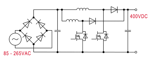
Interleaved Boost PFC
Description
By shifting the phase of the two boost converters by 180 degrees, it is possible to reduce the current stress in the inductors and switches, as well as the ripple current in the capacitors. This topology is useful for high power applications (several kW).
Overview
- Low noise & large power output
- Efficiency around 98%
- Frequency 70 kHz to 130 kHz
- Needs larger PCB space due to higher part count
Circuit

Key Products
| Product Category | Product family | Product Number | Feature |
|---|---|---|---|
| Switching Transistor | 600 / 650V SJ MOS | R60xxKN /R65xxKN | Good compromise between performance and ease of use. |
| 650 V IGBT | RGWxx series | IGBT proposal for lower cost, but comprising efficiency. | |
| Diodes | 650 V SiC SBD | SCS3xx series | Increased surge current mode capability of 3rd gen. |
| 650V Si FRD | RFS series | Lower Vf than RSV series, but ultra fast switching capability | |
| RFL series | Improve fast switching capability than RFN series. | ||
| 600 V Si FRD | RFV series | fast trr for CCM PFC (600V only)lower cost solution vs SiC SBD | |
| RFN series | low VF for DCM PFC (600V only) lower cost solution vs SiC SBD | ||
| Gate Driver | Isolated | BM61xxx Series | 1ch 3750Vrms isolated, for devices including driver source pin. |
| non-Isolated | BD2310G | 1ch non-isolated, simplest solution available. |
Simulation
A-006 : Interleaved Boost PFC VIN=200V, IIN=2.5A, CCM
Related Topologies

