Boost PFC
Description
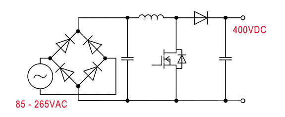
It is the simplest and most commonly used PFC circuit, consisting of a single boost converter. The desired current waveform can be generated by switching operation, and the power factor can be made close to one.
Overview
- Typically SJ MOSFET and SiC diodes (or FRD)
- Efficiency around 98%
- Frequency 70 kHz to 130 kHz
- Full load and nominal efficiency only guaranteed for 230 V AC
Circuit

Key Products
| Product Category | Product family | Product Number | Feature |
|---|---|---|---|
| Switching Transistor | 600 / 650V SJ MOS | R60xxKN /R65xxKN | Good compromise between performance and ease of use. |
| 650 V IGBT | RGWxx series | IGBT proposal for lower cost, but comprising efficiency. | |
| Diodes | 650 V SiC SBD | SCS3xx series | Increased surge current mode capability of 3rd gen. |
| 650V Si FRD | RFS series | Lower Vf than RSV series, but ultra fast switching capability | |
| RFL series | Improve fast switching capability than RFN series. | ||
| 600 V Si FRD | RFV series | fast trr for CCM PFC (600V only)lower cost solution vs SiC SBD | |
| RFN series | low VF for DCM PFC (600V only) lower cost solution vs SiC SBD | ||
| Gate Driver | Isolated | BM61xxx Series | 1ch 3750Vrms isolated, for devices including driver source pin. |
| non-Isolated | BD2310G | 1ch non-isolated, simplest solution available. |
Simulation
A-001 : Boost PFC VIN=200V, IIN=2.5A, BCM
A-002 : Boost PFC VIN=200V, IIN=2.5A, CCM
A-004 : Boost PFC VIN=200V, IIN=2.5A, DCM
Related Topologies

