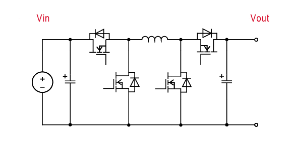
Bidirectional Buck-Boost converter
Description
Unlike the inverting backboost, it uses four switches (also two switches and a diode) to convert a positive input voltage into a positive step-down or boosted output voltage. The voltage conversion ratio M is determined by the on / off duty ratio D of the main switch and is given by the following equation.
M = D / (1-D).
Overview
- Bidirectional operation
- Buck Boost converter
- A lot of choice in switching device
Circuit

Key Products
| Product Category | Product Family | Product Number | Feature |
|---|---|---|---|
| Switch | 750V SiC MOSFET | SCT4xxxDx series | The latest SiC MOSFET device. Enhanced low on-resistance enable best in class performance. It supports 750 V withstand voltage, ensuring a higher operating margin than conventional products, and can be used safely. |
| 650V SiC MOSFET | SCT3xxxAx series | Trench-gate SiC MOSFET with low on-resistance (50% reduction) compared to conventional products. | |
| 650V IGBT | RGWxxTx65 series | Trench-gate and thin-wafer technologies are utilized to achieve low VCE(sat) reducing switching loss. | |
| 650V SJ MOSFET | R65 serires | 600 to 800V power MOSFETs using superjunction technlogy, enabling high speed switching and low on-resistance performance. Variaous choice of package are availble. | |
| Gate Driver | Galvanic Isolated gate driver | BM61x4xRFV | 1ch configuration, 3,750Vrms isolated type Gate Driver, can be used for switching devices with current source pins. |
Related Topologies

